
On my very first electric brew batch, i plugged the kettle element directly into the wall. Result: scorched element and badly burned flavored beer. Not a cool smokey flavor… an acrid “bread stuck in the toaster” flavor. That batch sadly made its way down the drain and the quest for an electric brewing controller began.
What’s a Controller?
A brewing controller typically has 2 modes: mash and boil. In mash mode, it basically functions as a glorified thermostat. It will control the amount of power delivered to the heater based on a temperature measurement of the wort. In boil, it lets the user manually adjust the power once boil is achieved. This prevents the element from going full power during the entire boil (kind of like how you lower the heat on the stove once the pasta water is boiling).
A typical brew session will have a temperature graph over time that looks something like this.
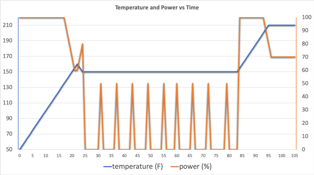
First, the controller turns the heater full on to get from cold water to mash temperature. When mash temperature is reached, the controller will turn on every so often at less than 100% power to maintain the mash temperature, which would otherwise slowly fall. Once mash is complete, the power goes to 100% so as to bring the the wort to a boil. Once building, the controller keeps the element on at a reduced power to maintain the rolling boil until the end. During the boil, there is no longer any temperature measurement (boiling is boiling) and the user adjust the power manually to maintain a rolling boil and avoid boil overs (or in my case walks away of to get a beer and runs back to clean up said boil over).
Solid State Relay
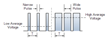
The brewing controller uses a scheme called PWM (pulse width modulation) to achieve this. For instance, to reduce the power to 80%, the controller will hold the element on 80% of a cycle and off the remaining 20%.
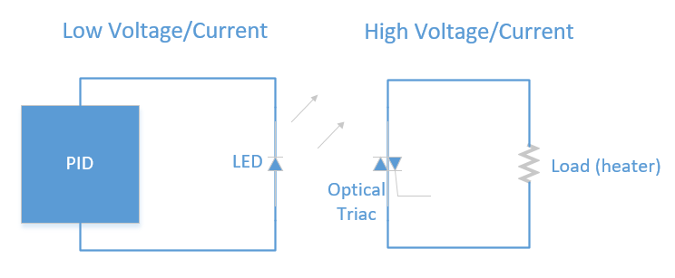
The brewing controller does not control the element directly. The PID is a low voltage device, while the the heater runs of 120V and draws over 18A of current. A switch called a solid state relay (SSR) is used instead. It has the ability to switch on and off rapidly and support the large currents drawn by the load. It isolates the low and high voltage circuits from each other. One way this can be done is optically. The PID controls an LED and an optical sensor turns on the high current path for the heating element. And that’s as far as we’re going to go into circuits and such.
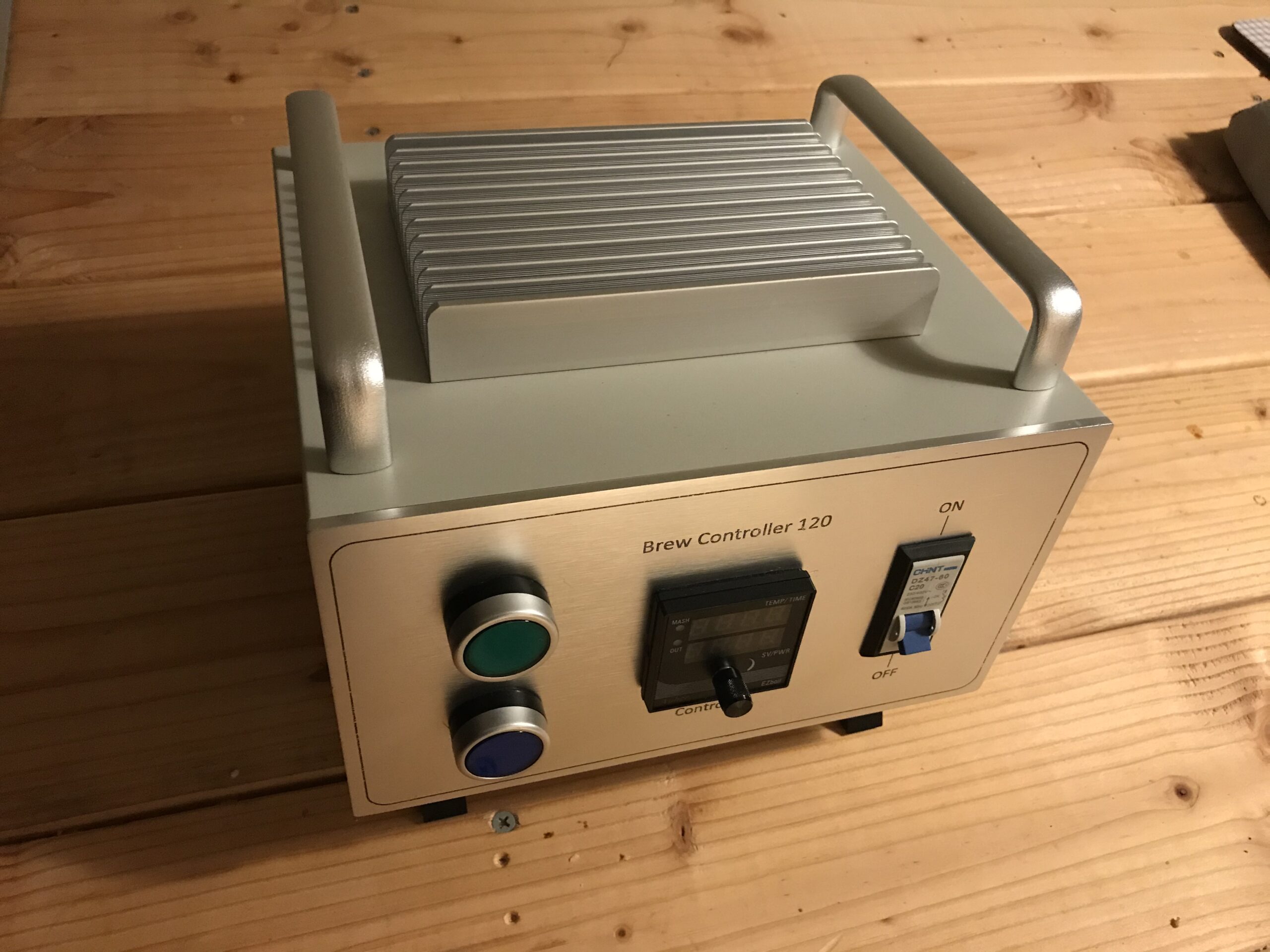
SSRs generate a fair bit of heat and need to be mounted to a heat sink for proper heat dissipation.
Most brewing controllers have built in “auxiliary” outlets and switches. In most cases this is to control a pump. As it happens, my recirculation pump does not have an on/off switch, so rather than plugging it in directly into the wall, I’ll add a 15A/120V outlet with a pump switch to the brew controller, for the pump to plug into.
What’s out there?
As noted in this post, I chose to go with a 2250W heating element. This then requires a brewing controller that will run off 120VAC and support 20Amps of current. A quick survey of what is available out there will come up with a list resembling this one:
| Vendor | Price($) | Voltage/Amperage |
|---|---|---|
| SS Brewtech | 599 | 240/30 |
| Clawhammer | 199 | 120/15 |
| Clawhammer | 699 | 240/30 |
| Blichmann | 375 | 120/15 or 240/30 |
| Electric Brewing | 575 | 240/30 |
| Auber | 370 | 120/20 |
| Auber | 435 | 240/30 |
| Auber | 420 | 240/30 |
| Auber | 540 | 240/30 |
Note that most available solutions are 240V/30A ones. This is very popular amongst brewers, especially those making 10 gallon batches or more. However it does require more serious electrical work as you basically need a dryer outlet and circuit installed in your brewspace (often your kitchen).
The only 120/20 offerings are from Auber Instruments and comes in $370. going DIY will save us anywhere between $100 and $200, depending on choice of components. Furthermore, upgrading it to 240V/30A will basically require a bit of rework and an extra $50 in parts. Future project!
My Build
The inspiration for my controller is the Auber Cube. It’s a cool looking 240/30 table top controller. It costs $420 for the old version, the new version being $540.
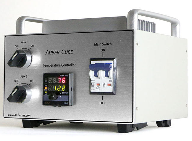
Interestingly, Auber sells a DIY kit for $300, but only for the 240V/30A version. Since i am going 120V, that won’t be an option.
Auber sells the raw enclosure for the cube, which will be my starting point. As an added bonus, it comes with a nice big heat sink to mount the SSR to. The following is the controller schematic/wiring diagram. It’s inspired by the wiring diagram that Auber provides for free on their website (to go with their DIY kit) and many nice schematics drawn by the good folks at the homebrewtalk.com forum. A wealth of information can be found in the various electric brewing threads.
Wiring Diagram
Following is the wiring diagram I will be using.
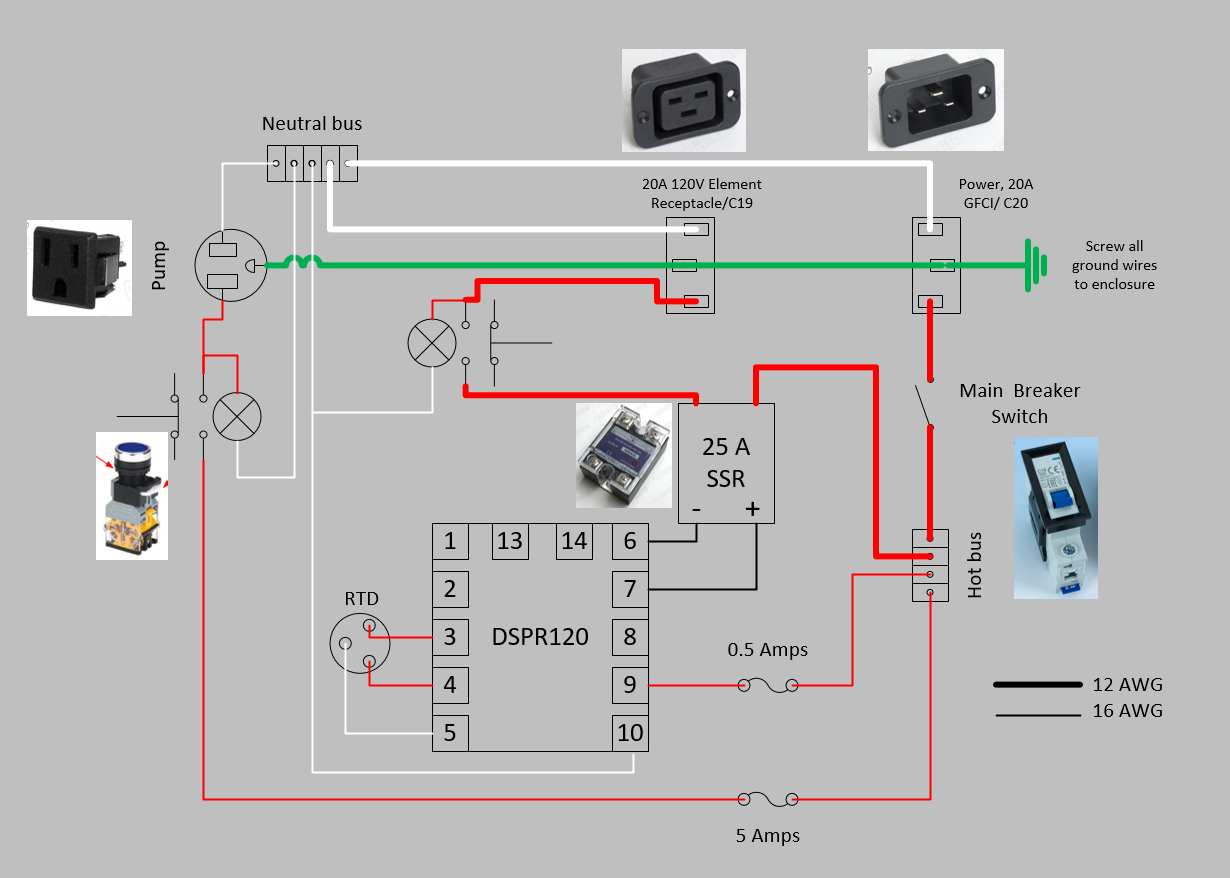
The power comes in through the C20 plug and goes straight to the main breaker switch. This is effectively the ON switch for the whole box. From there the live and neutral connections go to power the temperature controller, the pump outlet and the SSR driving the element.
Two push button LED switches are used. One to turn on the pump and one to connect the element. I opted for a switch to connect/disconnect the element so that the controller can be left on when heating is no longer needed, without needing to physically disconnect the element cable. An application of this can be to keep measuring and displaying your temperature as you are chilling the wort and no longer have a need for the heater. Yes you could also set the controller to mash the temp to 70F, but that’s more hassle than just hitting the button.
The LED across the element button is useful to indicate any issues we may be having with the SSR. SSR are known to get stuck closed, meaning that the heat is being applied even if the controller says to turn it off. This is not a good situation as a lot of heat can be applied at a time when we don’t expect any. the PID itself has an indicator which shows when the element is being switched on via the SSR. Should that indicator and the LED on the button not match (indicator on PID is off or flashing while button LED is solid on), then we immediately know there’s a problem and can hit the main breaker switch.
Part List and Panel layout
Let’s start by collecting a component list and lay out the front and back panels of the brewing controller.
| Component | Link | Price($) |
|---|---|---|
| Main Power breaker switch | Auber | 8.99 |
| Pump LED push button | Auber | 11.98 |
| Element LED push button | Auber | 11.98 |
| Element button 10A extension | Auber | 7.65 |
| SSR | Auber | 9.95 |
| Temperature controller | Auber | 46.95 |
| Temperature probe with wires and connectors | Auber | 44.99 |
| Pump outlet | Auber | 1.95 |
| Power inlet | Auber | 2.30 |
| Element outlet | Auber | 2.50 |
| Enclosure+Heatsink | Auber | 79.00 |
| Fuses and Holders | Amazon | 9.99 |
| Wire splices (20A rated) | Amazon | 9.45 |
| Wire Connectors | Amazon | 16.99 |
| Wiring 12 gauge | Amazon | 12.98 |
| Wiring 16 gauge | Amazon | 9.98 |
| TOTAL | 287.63 |
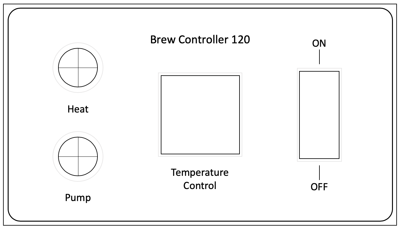
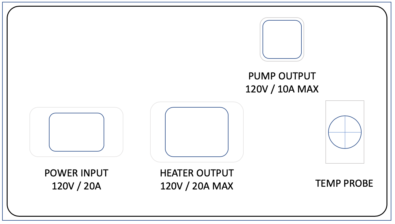
I laid out the front and back of the brewing controller as follows (using power point)
I put together some cardboard panels and cut out holes for the components, to make sure everything would fit inside the box properly. It’s unpleasant to discover that things don’t fit AFTER you’ve drilled all the holes.
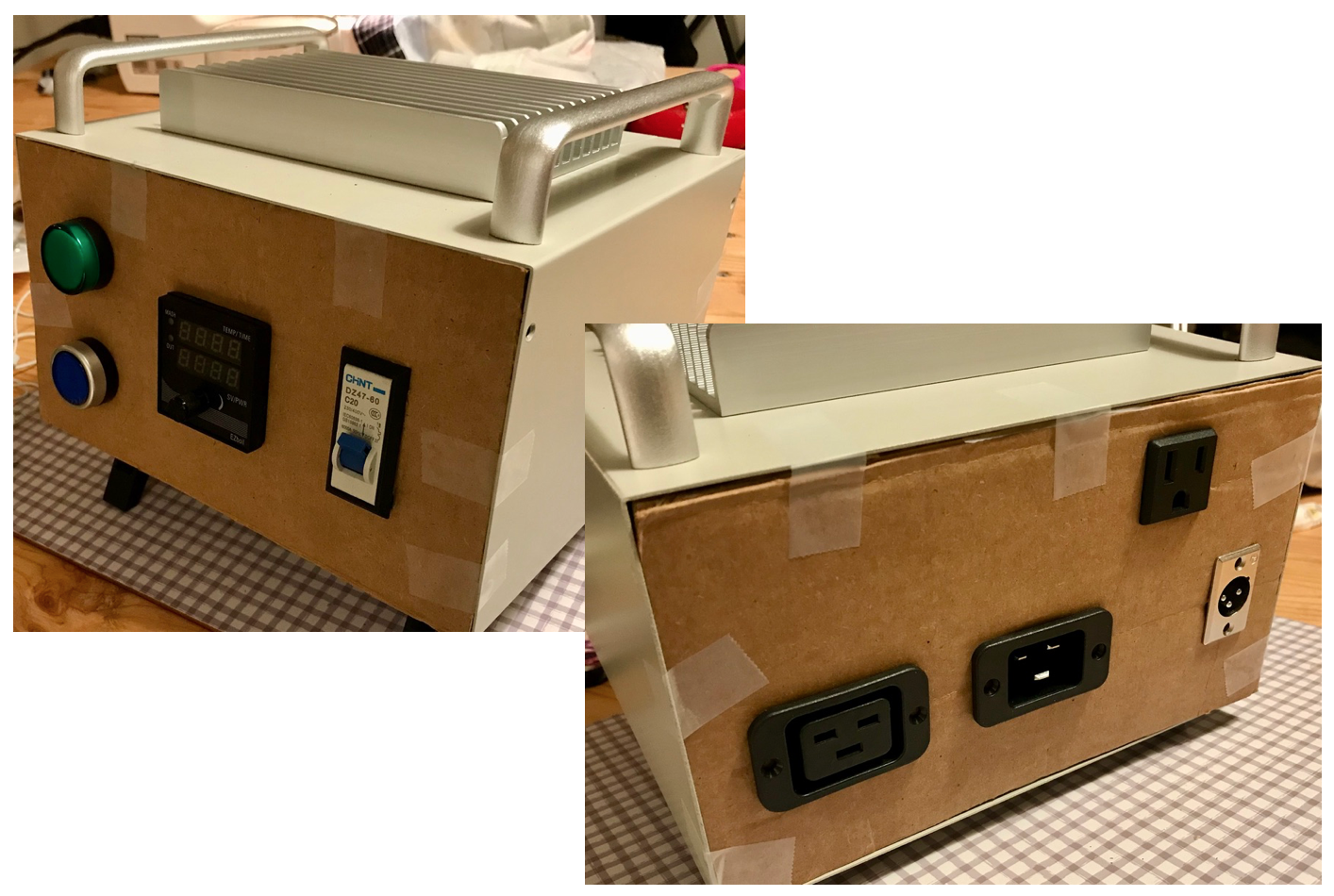
I sort of enjoy the ghetto look…
Drilling Holes
And now for the fun part of drilling the holes. The box is made of aluminum which is nice and soft. However, the front plate is a good few millimeters thick.
I’ll make 2 1/2″ holes in the front. For this is just got a fat 1/2″ drill bit on amazon. It did not do the cleanest job but it worked. A hole saw would have probably been much smoother. A drill press with the large drill bit would have probably done a good job as well. Giant drill bit with a dinky hand drill… not the best combo.
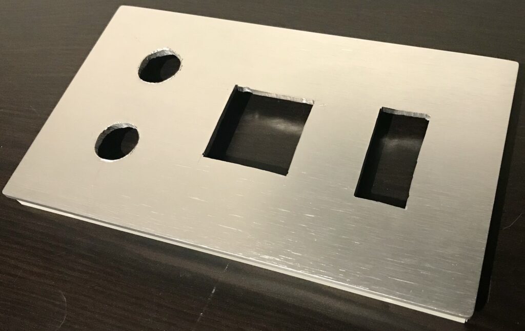
For the square holes, I used a jig saw with a metal blade. I first drilled 4 holes large enough to fit the jig saw blade in all corners of the square hole. Then cut from hole to hole with the saw. Finish up the edges with a few more passes. Auber has a document that explains this in detail. Here’s a fast motion of making the square hole for the PID.
The holes do not have to be perfect anyway, as the external part of the components are larger than the holes and will hide the imperfections. Here is a picture of my cut out front panel. The holes are rough, but once the components are fitted in, it’s all hidden away.
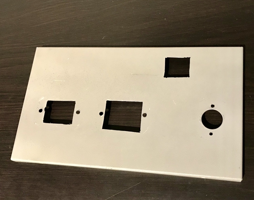
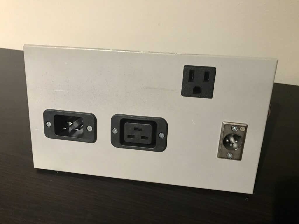
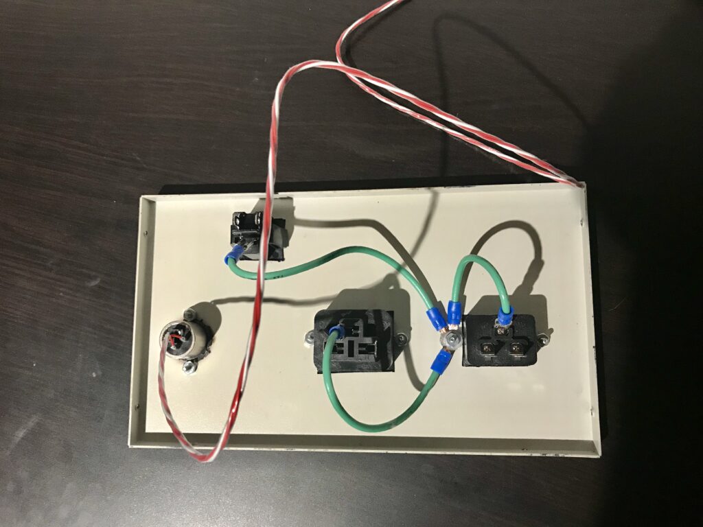
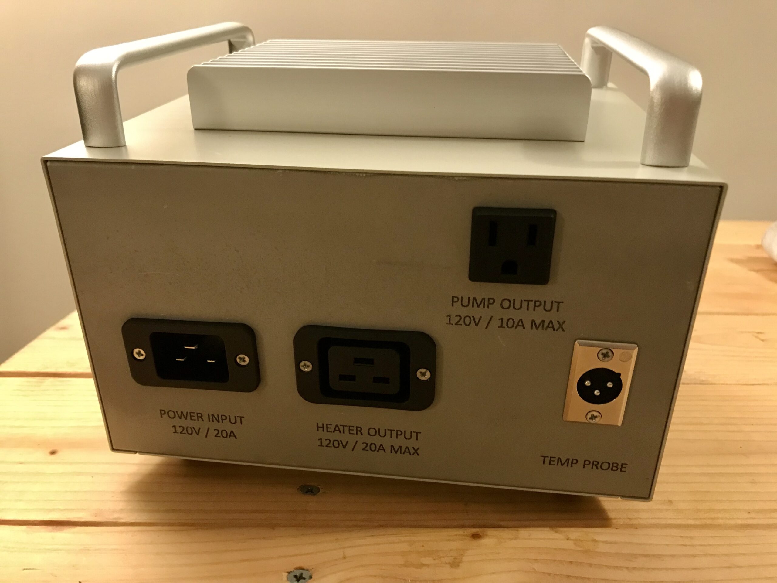
The back plate is significantly thinner and we follow the same procedure for the holes. I’ll need 3 rectangular holes for the inlet and outlets and one 1/2″ round hole for the temperature probe. Finally a few small holes for the C19/C20 sockets are needed to attache them to the enclosure with screws. I used #4-40 x 1/2 inch screws with nuts from Home Depot.
Wiring
Now for the wiring. Once the components are fitted, it’s time to wire stuff. We should differentiate between a few seperate circuits in our box in terms of supported currents. This dictates what wire gauge is needed. We can always use bigger than necessary wires, but never smaller. We could for instance wire the whole thing in 12 gauge wire. However it would be a pain as 12 gauge is less flexible and more difficult to work with.
- High Voltage High current. 120V, 20A: The power inlet, the heating element outlet, the breaker switch, the SSR and the heating element, the heating element switch. WIRE: 12 AWG
- High Voltage, Low current. 120V, <5A: The pump outlet, the pump outlet, the pump switch, the PID, both switch LEDs. WIRE: 16 AWG
- Low Voltage, Low current. ?V, <1A: The temp probe, the controls between the PID and SSR. WIRE: 16 AWG (could be 22 AWG, but 16 gauge is pretty flexible and saves us buying more wiring)
First, the grounds. The entire enclosure should be grounded, so that it is never under voltage, should anything go astray and a short created. If a loose wire was touching the enclosure it could shock whoever touches it. if the box is grounded, a lose wire touching the box will create a short to ground and trip the circuit breaker.
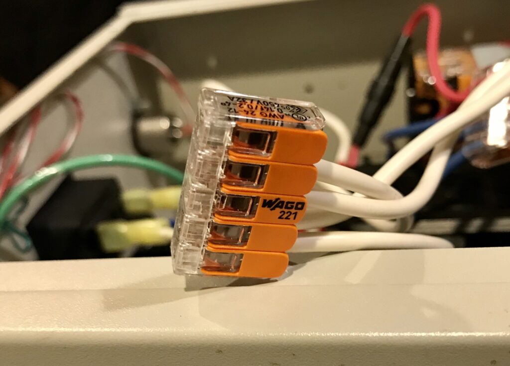
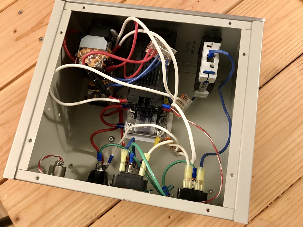
The rest of the wiring is follows the schematic. I used a rachetting crimp tool to attach wire connectors to wires. I used these nifty wire splicers to created neutral and hot buses, to distribute power around the box.
The final result looks a bit of a mess but we’ll be closing the box now!
Pannel Labels
For a little extra fancy pants factor, I used a toner transfer method used for PCBs to add some nice looking labeling on the front and back panels. Print the labels reversed on transfer paper (though I did a quick test with regular white paper and it seemed to work ok as well). Press it on your pannels with a hot iron for a couple of minutes, applying a lot of pressure. You should be able to do a half decent job transferring the toner. There are many youtube videos out there on toner transfer.
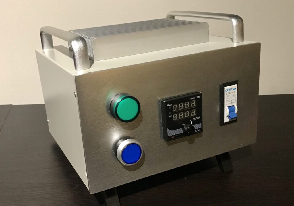
Final Build!
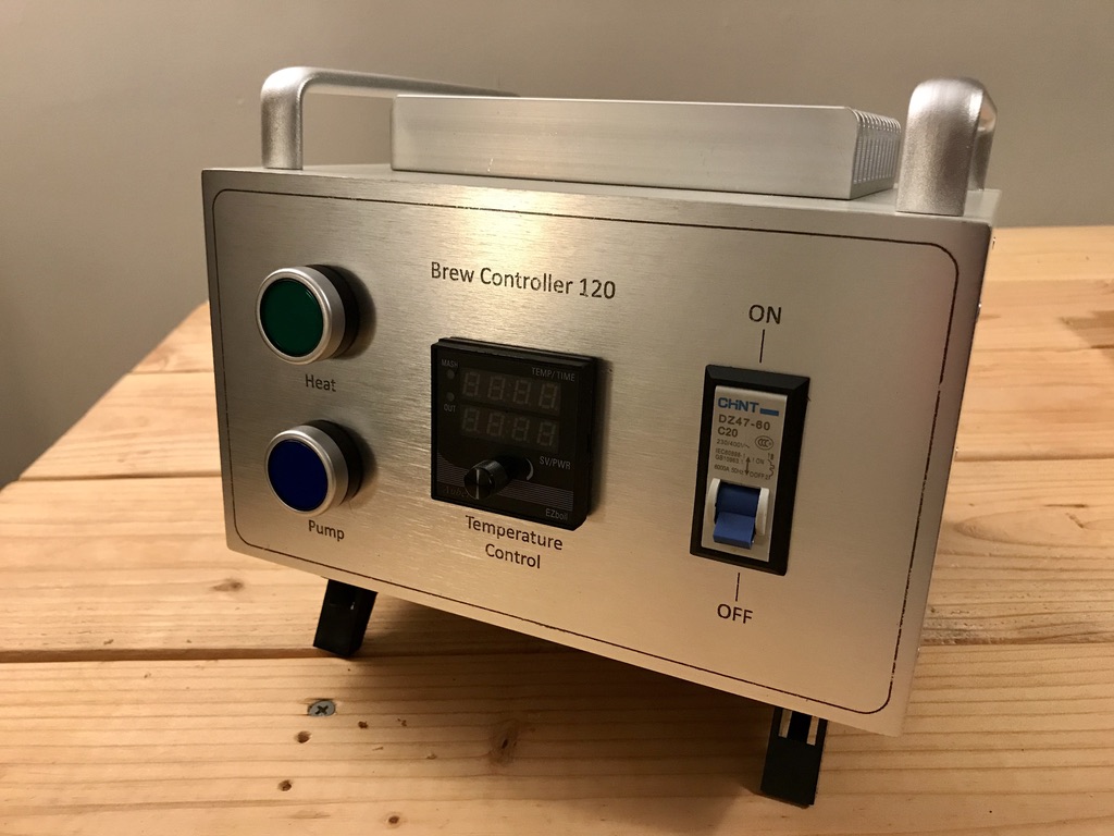
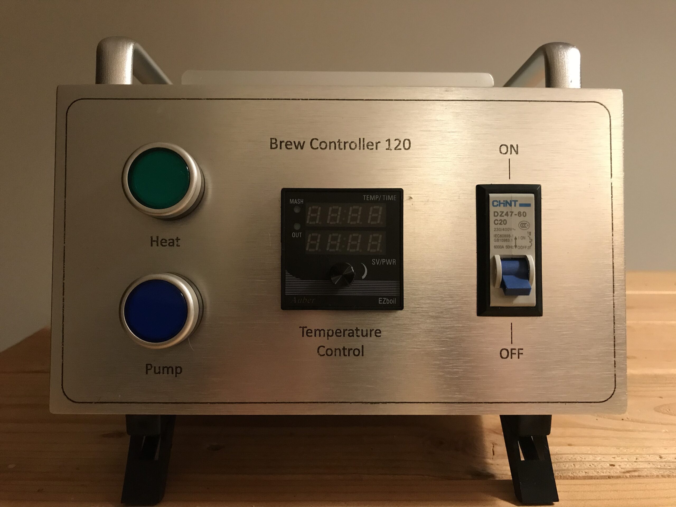
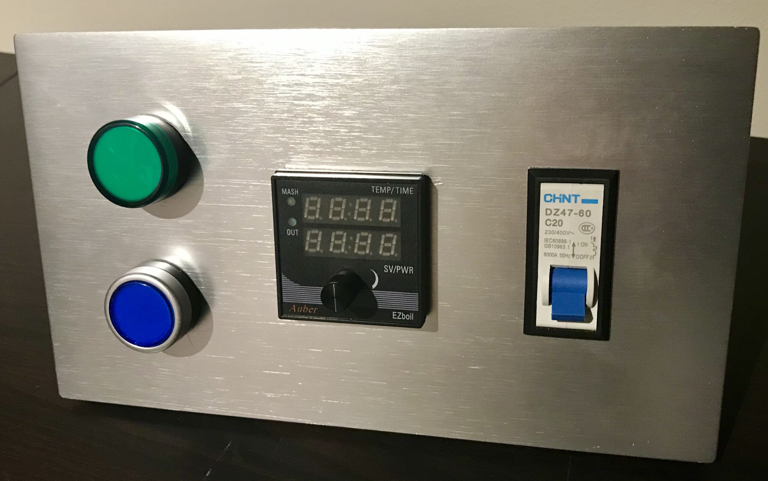
Make sure to check out the post on making the cables for this box, as well as how to replace your kitchen socket with a 20 amp one. Here’s the controller in action, maintaining mash temperature!
Tool list
| Tool | Link | Price($) |
|---|---|---|
| Ratcheting crimp tool | Amazon | 21.26 |
| Wire stripper | Amazon | 7.99 |
| 1/2″ drill bit | Amazon | 7.29 |
| Jig Saw | Amazon | 40.30 |
| Total | 76.84 |
*Note the initial version had an LED indicator for the element, instead of a button